

USB-045 CV-Monitor
User's Manual
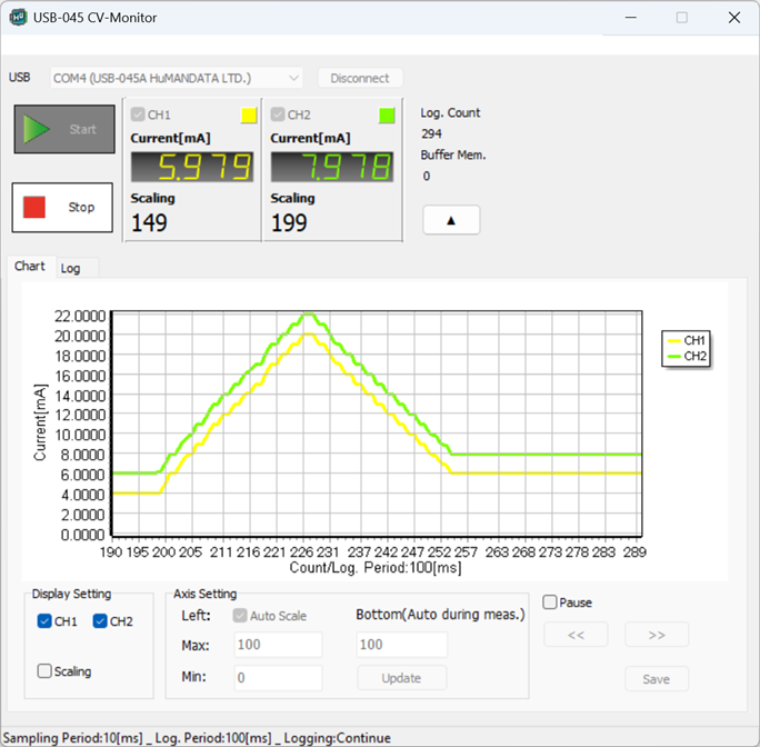
Overview
USB-045 CV-Monitor is a dedicated application for the following products:
Japanese website only. Available for sale in Japan only. For a related product, please consider the USB-050V.
This application runs on Windows and supports Windows 11 and Windows 10. It allows real-time display and logging of measured values (current or voltage) acquired via USB.
The application provides the following features:
- Display of measured values (current or voltage) and scaled values
- Real-time chart display
- Measurement log display
- Scaling configuration
- Sampling and logging interval configuration
- CSV file generation and export
and more
The maximum number of measurement records that can be displayed within the application is 500,000. However, by enabling the "Export to CSV" option in the settings screen and disabling both "Chart Display" and "Log Display", it is possible to save more than 500,000 measurement records directly to a CSV file.
The number of measurement records that can be saved to a CSV file is typically several million. However, the actual maximum number depends on factors such as available PC memory capacity and storage performance. Therefore, verification on the target system is recommended.
Installation
The following example describes installation on Windows 11.
- Download "USB-045 CV Monitor" from the product documentation page and run "Setup_USB-045 CV-Monitor Ver*.*.exe".
- A User Account Control dialog will appear. Click [Yes].
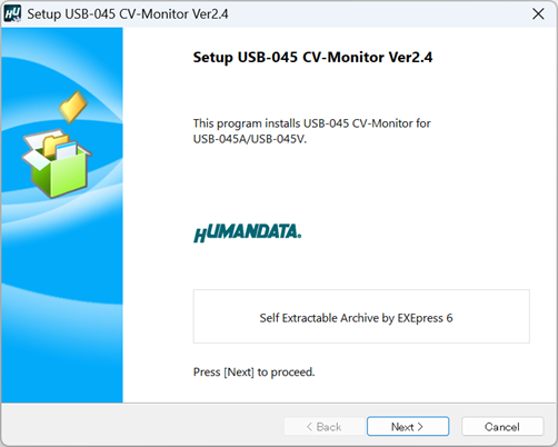
- The installer window appears. Click [Next].
- Specify the destination folder and click [Next].
The default folder name is: "HuMANDATA¥USB-045 CV-Monitor"
If the destination folder is changed, the "Add default folder" option becomes available.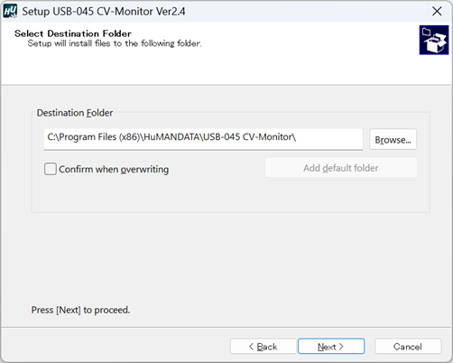
- The Ready to Install screen appears. Confirm the contents and click [Next]. If necessary, check "Create shortcut on Desktop". (Disabled by default.)
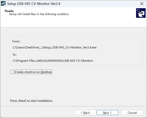
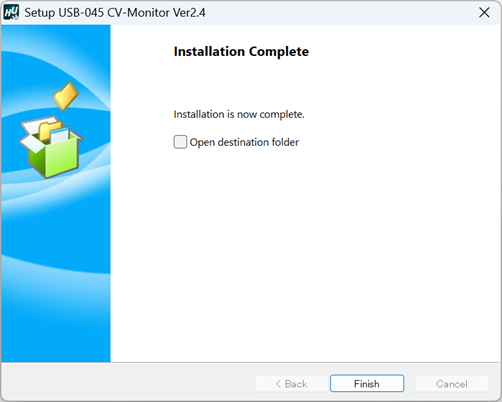
- The installation will begin. When the Installation Complete screen appears, click [Finish] to close the installation wizard.
Uninstallation
The following procedure describes uninstallation on Windows 11.
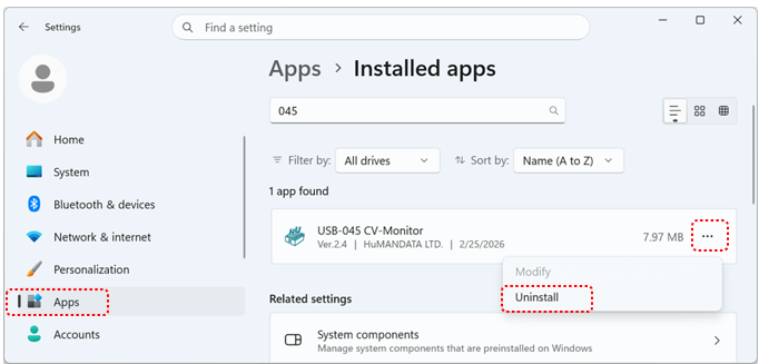
- Open Settings > Apps > Installed Apps. Select USB-045 CV-Monitor from the list and click [Uninstall] from the [...] menu.
- A User Account Control dialog appears. Click [Yes].
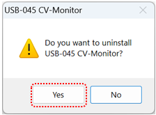
- A confirmation screen appears. Click [Yes] to proceed.
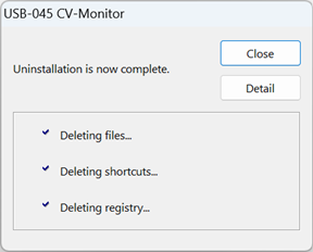
- When the Uninstallation Complete screen appears, click [Close].
The configuration file of this application is not automatically deleted during uninstallation so that it can be reused after reinstallation. If the configuration file is no longer needed, delete the following file manually:
C:\Users\(UserName)\AppData\Roaming\HuMANDATA\USB-045\USB-045.ini
Operation
Common Screen
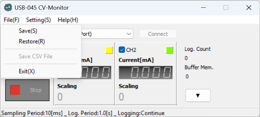
Displayed by clicking [File(F)] in the top menu.
| Item | Description |
|---|---|
| Save(S) | Saves the current settings to a configuration file. |
| Restore(R) | Loads a configuration file. |
| Save CSV File | Manually saves the CSV file. This function is enabled only when "Export to CSV" is checked on the CSV tab of the Settings screen. For details, refer to Section "4.4.5. CSV Screen". |
| Exit(X) | Exits the application. |
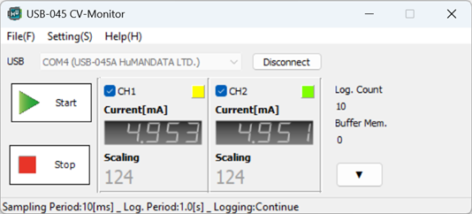
| Item | Description |
|---|---|
| Port Connect / Disconnect | Connects to or disconnects from the device. Select the COM port to which the USB-045A or USB-045V is connected from the pull-down menu. |
| Start | Starts measurement. This button is enabled only when a connection to the device has been established. While measurement is in progress, the top menu is hidden. |
| Stop | Stops measurement. |
| ☑ [CH1] / ☑ [CH2] | The checked channels will be included in the measurement. |
| ▼/▲ | Shows or hides the Chart/Log display area. |
| Log. Count | Displays the number of logged measurements. |
| Buffer Mem. | Displays the buffer memory usage status. Measurement data is temporarily stored in the buffer when the PC cannot save data quickly enough due to PC performance limitations or the configured sampling interval. |
Chart Display Area
This area displays measurement data in chart form. The maximum number of plot points that can be displayed is 500,000 points.
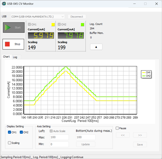
| Item | Description |
|---|---|
| ☑ [CH1] / ☑ [CH2] | Displays the chart for the selected channel(s). |
| ☑ Scaling | Checked: The vertical axis displays the scaled value. Unchecked: The vertical axis displays the measurement value. |
| Left: ☑ Auto Scale | When checked, the vertical axis scale is adjusted automatically. |
| Max. | Sets the maximum value of the vertical axis. Available only when Auto Scale is unchecked. |
| Min. | Sets the minimum value of the vertical axis. Available only when Auto Scale is unchecked. |
| Bottom (Auto during meas.) |
To manually change the horizontal axis scale, modify this setting while measurement is stopped or paused.
Note: During measurement, the horizontal axis scale is automatically adjusted.
|
| Update | Updates the chart after changing the vertical or horizontal axis settings. |
| Pause | Temporarily pauses chart updates. |
| << / >> | Scrolls the horizontal axis left or right. Available only when measurement is stopped or paused. |
| Save | Saves the currently displayed chart as a bitmap (BMP) image file. |
Log Display Area
This area displays measurement data in log format. The maximum number of log entries that can be displayed is 500,000 records.
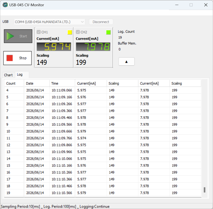
Settings Screen
This screen is displayed by selecting [Settings (S)] from the top menu.
Basic Settings (When USB-045A Is Selected)
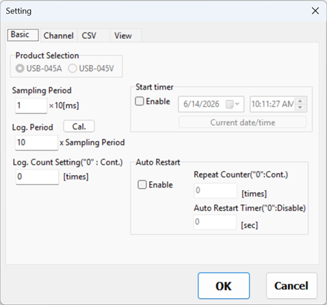
Note:
For long-term logging applications, it is recommended to configure the Windows power settings to prevent the PC from entering Sleep mode before starting measurement. If the PC enters Sleep mode during measurement and USB communication is interrupted, an error may occur and the measurement may not be completed correctly.
Channel Settings (When USB-045A Is Selected)
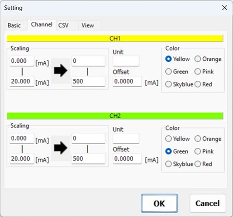
| Item | Description |
|---|---|
| Scaling | Sets the scaling range. Decimal values and negative values can be entered. The maximum number of digits for a scaling value is 7. The number of decimal places must be the same for both CH1 and CH2. |
| Unit | Sets the engineering unit. The maximum length is 5 characters (including up to one double-byte character). |
| Offset | Sets the offset value. Decimal values and negative values can be entered. The offset is added to the measured value before display and logging. |
| Color | Sets the display color for the channel. |
Basic Settings (When USB-045V Is Selected)
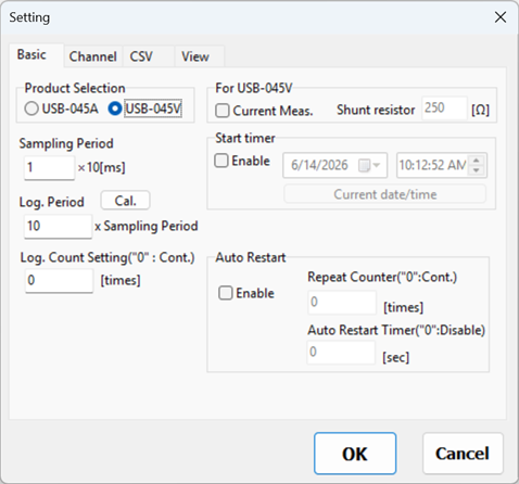
| Item | Description | |
|---|---|---|
| Product Selection | Select USB-045V. If the USB driver has been installed and the device is connected, it will be selected automatically. | |
| Current Meas. | Check this option when measuring current using an external shunt resistor. When enabled, the measured values displayed on the main screen will be shown as current values. | |
| Shunt resistor | Enter the value of the external shunt resistor. | |
| Sampling Period | Sets the sampling period. The unit is [ms (×10)]. | |
| Log. Period | Sets the multiplier used to calculate the logging interval. The actual logging interval is calculated as the sampling interval multiplied by this value. | |
| Cal. | Calculates the logging interval [ms] and displays the result on the right side. | |
| Log. Count Setting("0":Cont.) | Sets the number of logging operations. When set to "0", measurement continues until the Stop button is pressed. | |
| Start timer ☑ Enable |
Check this option and specify a date and time to start measurement automatically at the designated time. | |
| Auto Restart | ☑ Enable | Enables the automatic restart measurement function. |
| Repeat Counter ("0":Cont.) |
Sets the number of automatic restart measurement cycles. When set to "0", operation continues until the Stop button is pressed. The maximum setting is 10,000. For example, if the log. count is set to 1,000 and the repeat counter is set to 10, the application automatically performs 11 measurement cycles of 1,000 samples each. | |
| Auto Restart Timer ("0":Disable) |
Sets the delay before automatic restart measurement starts. The unit is [sec]. A setting of "0" disables this function. The maximum setting is 86,400 seconds (24 hours). | |
Note:
For long-term logging applications, it is recommended to configure the Windows power settings to prevent the PC from entering Sleep mode before starting measurement. If the PC enters Sleep mode during measurement and USB communication is interrupted, an error may occur and the measurement may not be completed correctly.
Channel Settings (When USB-045V Is Selected)
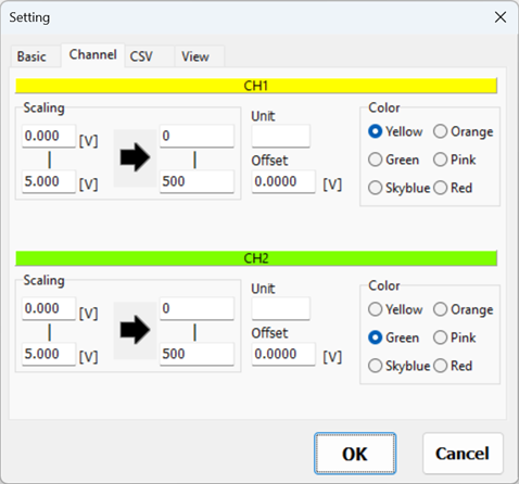
| Item | Description |
|---|---|
| Scaling | Sets the scaling range. Decimal values and negative values can be entered. The maximum number of digits for a scaling value is 7. The number of decimal places must be the same for both CH1 and CH2. |
| Unit | Sets the engineering unit. The maximum length is 5 characters (including up to one double-byte character). |
| Offset | Sets the offset value. Decimal values and negative values can be entered. The offset is added to the measured value before display and logging. |
| Color | Sets the display color for the channel. |
CSV Screen
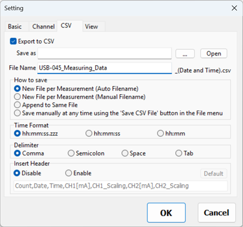
| Item | Description |
|---|---|
| ☑ Export to CSV | Check this option to export measurement data to a CSV file. |
| ... | Specifies the destination folder for CSV file storage. |
| Open | Opens the folder where CSV files are saved. |
| File Name | Specifies the CSV file name (excluding the file extension). |
| How to Save | Selects how CSV files are saved.
|
| Time Format | Specifies the date and time format used in the CSV file. |
| Delimiter | Specifies the delimiter character used in the CSV data. |
| Insert Header | To insert a header row at the beginning of the CSV file, select Enable and specify the header content.
|
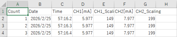
The CSV file format is as follows:
[Logging Count, Date, Time, CH1 Measured Value, CH1 Scaled Value, CH2 Measured Value, CH2 Scaled Value]
The unit of current values is [mA], and the unit of voltage values is [V].
Examples of CSV file output are shown below.
- Example 1: When "Insert Header" is set to "Disable"

- Example 2: When "Insert Header" is enabled and the header content is set to the default value
- Example 3: When "Insert Header" is enabled and "Save Method" is set to "Append to Same File"
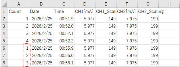
The logging count is appended sequentially as 1, 2, 3, ... from the start of each measurement session.
The header is inserted only when a new CSV file is created.
By disabling "Chart Display" and "Log Display" in the Display tab described in the next section, it is possible to save more than 500,000 measurement records to a CSV file.
The number of measurement records that can be saved to a CSV file is typically several million. However, the actual maximum number depends on factors such as available PC memory capacity and storage performance. Therefore, verification on the target system is recommended
View
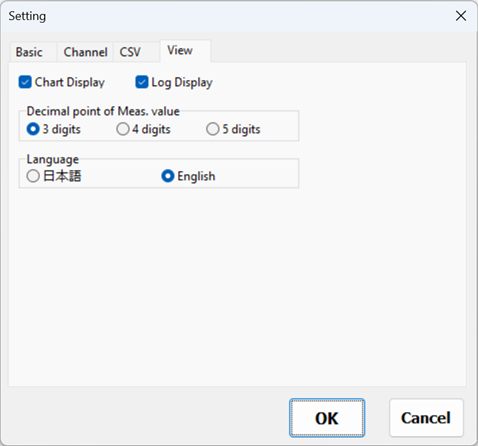
| Item | Description |
|---|---|
| ☑ Chart Display | Check this option to display the chart. |
| ☑ Log Display | Check this option to display the log. |
| Decimal point of Meas. Value | Sets the number of decimal places displayed for measured values. |
| Language | Select the display language: Japanese or English. |
Help
Click [Help (H)] on the top menu to display the Version Information window.
Configuration File
The configuration file is automatically saved when the application is closed. It will be loaded automatically the next time the application is started.
C:\Users\(UserName)\AppData\Roaming\HuMANDATA\USB-045A\USB-045A.ini
The configuration file is not deleted during uninstallation so that settings can be reused.
To load the setting on another PC, delete it manually if it is no longer required.
Select "File(F) > Save(S)" and save the configuration file.
On another PC, select "File(F) > Restore(R)" and load the saved configuration file.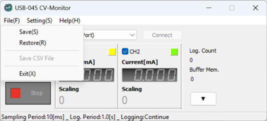
Automatic Measurement Using Command-Line Arguments
By using command-line arguments, the following sequence of operations can be performed automatically:
- Launch the application
- Connect to the USB (COM port)
- Start measurement
- Complete the specified number of measurements
- Save the measurement data to a CSV file
- Disconnect the USB (COM port)
- Exit the application
Before using this feature, configure the required settings such as Log. Period and Export to CSV in Section 4.4 Settings.
Command-line arguments can be specified in one of the following ways:
- In the Target field of the application's shortcut (Properties > Shortcut > Target)
- From an external program such as Windows Task Scheduler
- In a batch (.bat) file
<Syntax>
C:\Program Files (x86)\HuMANDATA\USB-045 CV-Monitor\USB-045 CV-Monitor.exe [COM Port Number] [Measurement Count] [Option]
To automatically exit the application after the specified number of measurements has been completed, specify "/s" as the optional argument.
<Example>
C:\Program Files (x86)\HuMANDATA\USB-045 CV-Monitor\USB-045 CV-Monitor.exe 5 10 /s
This command performs the following operations automatically:
- Launches the application.
- Connects to COM5.
- Acquires 10 measurements and saves the data to a CSV file.
- Disconnects from COM5.
- Exits the application automatically.
Reference Materials
Updated documentation and additional reference materials will be published on each product page as needed.
You may also find useful information on the following support page:
Revision History
| date | Version | Description |
|---|---|---|
| 2026/07/23 | 1.0 | Initial release |
